Introduction
If you've ever looked at a sloped backyard and wondered how to turn it into a usable patio or pool deck, a cantilever retaining wall is probably the answer. These walls use a reinforced vertical stem and a projecting footing to hold back soil while creating level, usable ground on a hillside.
Design quality isn't optional here. Soil pressure, groundwater, surcharge loads, and poor drainage all affect whether a wall stays put or fails within a few years.
Under the 2024 International Building Code, retaining walls must resist overturning, sliding, excessive foundation pressure, and water uplift. In higher seismic zones, walls over 6 feet tall need additional lateral earth pressure calculations (IBC Chapter 18).
This article covers the main cantilever wall types, their structural components, the design checks engineers run, and how to choose the right system for your site.
Key Takeaways
- Cantilever walls resist soil pressure through the combined action of the stem, footing, and soil weight over the heel.
- Common variations include cast-in-place concrete, reinforced masonry, precast panels, and counterfort-modified designs.
- Design requires site-specific soil, water, and load data — not generic height charts.
- Stability hinges on four checks: sliding, overturning, bearing pressure, and global slope stability.
- Drainage failure is one of the most common causes of wall movement and cracking.
What Is a Cantilever Retaining Wall—and Why Does It Matter?
A cantilever retaining wall is a reinforced concrete or masonry structure that resists lateral soil pressure with a projecting footing, acting much like a cantilever beam. Instead of relying on sheer mass like a gravity wall, it relies on leverage: the footing extends under the retained soil, and that soil’s weight helps hold the wall down and in place.
The Core Components
Every cantilever wall shares a few basic parts:
- Stem: the vertical member that retains the backfill and bends under soil pressure
- Footing (base slab): the horizontal foundation, split into heel and toe zones
- Heel: the footing portion beneath the retained soil, behind the stem
- Toe: the footing portion on the exposed side, in front of the stem
- Shear key (optional): a projection below the footing that boosts sliding resistance when friction isn’t enough

How the Wall Actually Works
Soil pressure pushes against the stem, creating bending and shear forces that want to tip the wall forward and slide it out of position. The footing counters this in two ways: the toe provides some bearing resistance, and the heel , plus the weight of the soil on top of it, anchors the wall against overturning and sliding.
Where These Walls Make Sense
Cantilever walls show up constantly in hillside construction projects, including:
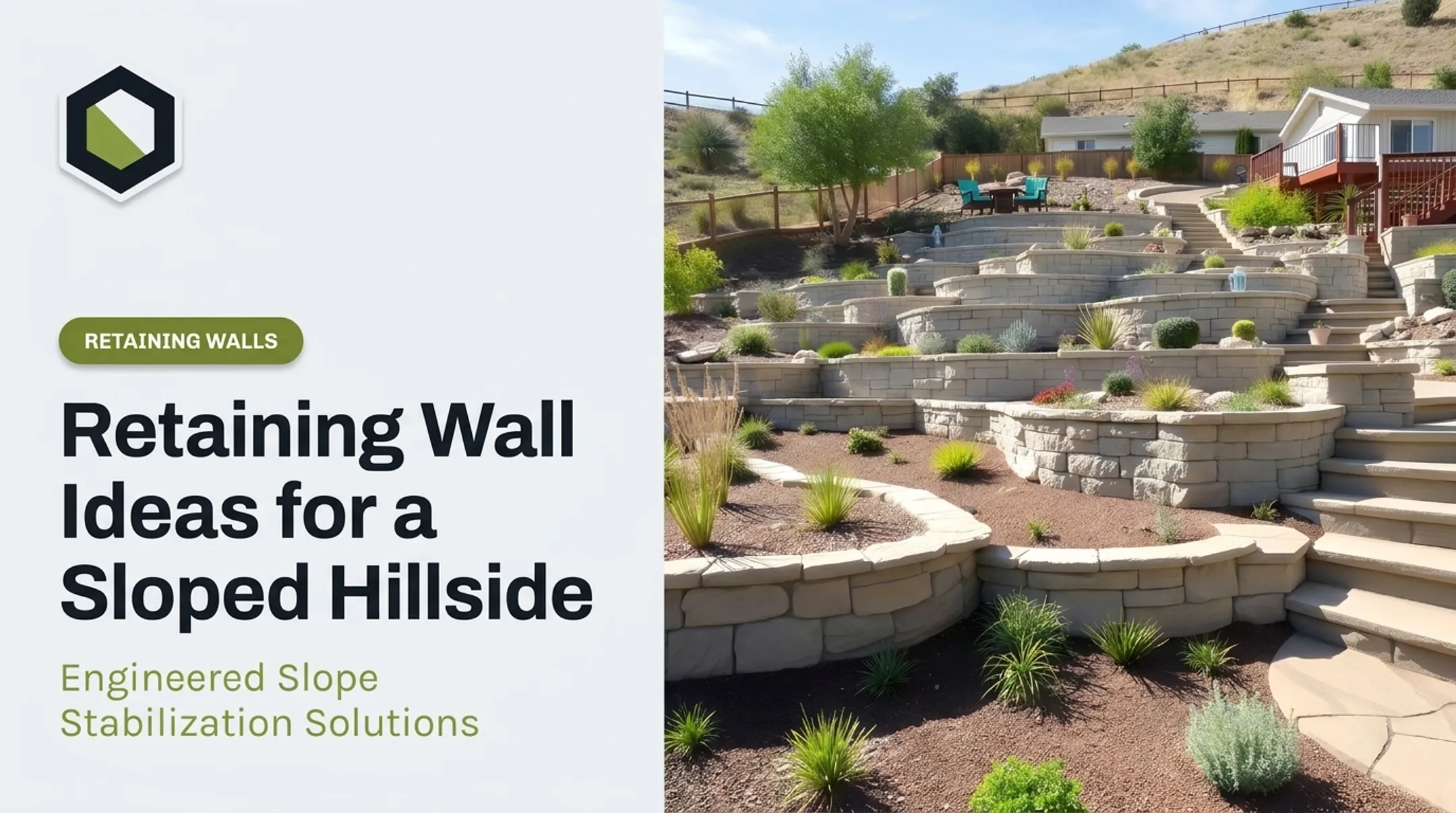
- Terracing steep backyards into flat, usable levels
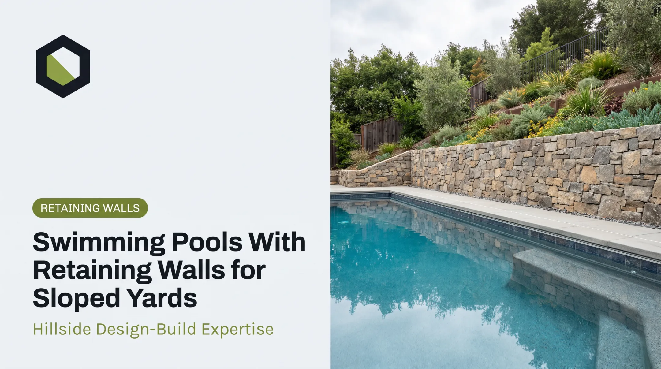
- Supporting driveways, patios, or pool decks cut into a slope
- Protecting lower structures from erosion or slope movement
- Creating retaining structures for garden beds or seat walls
Compared with a massive gravity wall, a cantilever design uses less concrete and a smaller footprint for the same retained height. The trade-off is tighter engineering, reinforcement detailing, and construction quality control.
A cantilever wall isn’t automatic for every site. Fit depends on:
- Retained height
- Soil type and groundwater
- Nearby structures
- Local code triggers
Types of Cantilever Retaining Walls
Cantilever retaining walls come in several configurations. Material, reinforcement layout, and structural shape often overlap on the same residential or hillside project.
Cast-in-Place Reinforced Concrete Cantilever Walls
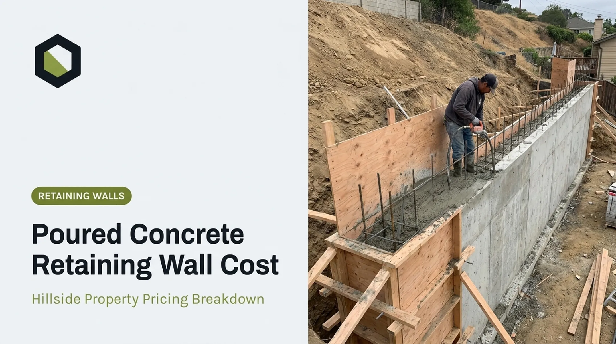
This is the classic L-shaped or inverted-T cantilever wall. Reinforcing steel ties the stem to the footing so they act as one unit, resisting bending and shear together.
This option tends to suit residential hillside projects where the site allows for excavation, formwork, and cure time. Trade-offs include:
- Formwork and excavation labor
- Reinforcement placement and inspection before pour
- Concrete curing time before backfill can proceed
- Site access needed for concrete trucks or pumps
Reinforced Masonry Cantilever Walls
Reinforced concrete masonry units (CMU), grout, vertical reinforcement, and a concrete footing combine into a structural system. Vertical bars set in grouted cores resist the tensile stresses created by lateral earth pressure (NCMA TEK 15-7B).
Masonry offers modular construction and finish flexibility. It is not a lighter-duty substitute for cast-in-place concrete. Design still has to address:
- Block strength and grout consolidation
- Reinforcement placement and footing behavior
- Drainage detailing
- Applicable masonry code requirements
Precast or Modular Cantilever Wall Systems
Factory-produced panels reduce on-site forming and support consistent fabrication quality. That said, precast isn't automatically faster or cheaper. It requires:
- Transportation and lifting access for crane equipment
- Joint and connection design between panels
- Prepared, level bearing surfaces
- Local availability of the specific system
Many precast systems specify high-strength concrete (for example, 7,000 psi) and Grade 60 reinforcement designed under AASHTO LRFD. They follow their own detailed specifications, not a generic template.
Counterfort-Modified Cantilever Walls
For taller or heavily loaded walls, counterforts — triangular or vertical webs behind the stem — tie the stem and footing together and reduce bending demand. They become worth considering when wall height or surcharge loads push a standard cantilever design past practical limits.
The trade-off: counterforts add excavation, reinforcement coordination, and formwork complexity, plus a more noticeable visual footprint behind the wall.

Quick note on scope: Cantilever walls are one retaining system among several. Other options work differently and are not interchangeable with a cantilever design:
- Gravity walls
- Embedded (sheet pile) walls
- Mechanically stabilized earth (MSE) walls
- Soil-nail systems
- Segmental block walls
How Are Cantilever Retaining Walls Designed?
Design starts with site information, not a preferred wall type or a dimension pulled from a chart.
Site and Soil Investigation
Before anything gets drawn, an engineer needs to establish:
- Retained height and wall geometry
- Foundation soil bearing capacity and friction characteristics
- Groundwater level and slope stability
- Settlement risk and proximity to existing foundations or utilities
Local permit triggers vary widely. Portland, Oregon requires stamped engineering for walls over 4 feet; Douglas County, Colorado uses the same 4-foot/surcharge trigger; Prince George's County, Maryland requires permits above 2 feet with geotechnical borings. There's no universal height threshold. Confirm requirements with your local building department.
Loads and Lateral Earth Pressure
Soil pushes against a wall in three possible states (active, at-rest, and passive), depending on how much the wall moves. Active pressure develops after relatively small wall movement away from the backfill, while passive pressure requires movement roughly ten times larger (SCDOT Geotechnical Design Manual).
The design must also account for:
- Backfill slope angle and soil density
- Surcharge from driveways, structures, pools, or equipment
- Groundwater pressure behind the wall
- Seismic loading, where required by code
Stability Checks
Four checks determine whether a cantilever wall design works:
- Sliding: does friction and shear key resistance exceed the lateral push?
- Overturning: does the resisting moment exceed the overturning moment?
- Bearing pressure/eccentricity: does soil pressure under the footing stay within allowable limits?
- Global slope stability: does the wall-and-slope system stay stable as a whole?

Design references vary in their factor-of-safety targets (masonry guidance from NCMA calls for a minimum 1.5 against both overturning and sliding), but the controlling load case and governing code always dictate the final numbers on a specific project.
Structural Design of Wall Components
The stem is designed primarily for bending and shear, since it acts like a vertical cantilever beam. The heel and toe, by contrast, behave as footing elements loaded by soil pressure and vertical loads from above.
Reinforcement location differs by component. Bar size, spacing, development length, concrete cover, and material strength all come out of calculations specific to the wall's height, soil, and loads — not a generic rebar diagram borrowed from another project.
Drainage and Water Management
Water behind a wall adds hydrostatic pressure that the design usually is not built to resist, and it's a leading cause of cracking, movement, and outright failure. Proper drainage typically includes:
- Free-draining granular backfill
- Perforated collector drains with filter fabric where specified
- Weep holes or drain outlets at the wall face
- Surface grading to direct runoff away from the wall
This is also where field experience matters. Stonework Design & Build has found that missing or clogged drainage behind a wall is one of the most common and most preventable causes of retaining wall failure on Southern California hillside lots, alongside footing depths that don't match the actual soil and slope conditions.
Construction, Inspection, and Permitting
A typical build sequence runs:
- Survey and layout
- Excavation and foundation prep
- Reinforcement and formwork
- Concrete placement and drainage installation
- Cure time, then engineered backfill, compaction, and grading
Excavation safety, backfill timing, lift thickness, and equipment distance from the wall should all follow the engineered plans, not general assumptions.
A structural or geotechnical professional typically prepares or reviews the calculations and drawings, while the contractor coordinates site conditions, inspections, and permit sign-off.
How to Choose and What to Check Before Finalizing a Design
Choose the cantilever wall that fits the site's constraints and holds up for its full design life, not the most familiar or attractive option.
Evaluate before designing:
- Retained height, wall length, and available footprint
- Excavation limits and access for concrete trucks or lifting equipment
- Proximity to property lines, structures, and utilities
- Soil and groundwater conditions, surcharge loads, and seismic exposure
- Finish preferences and long-term maintenance expectations
Compare feasible alternatives with your design team:
- Standard cantilever wall
- Counterfort wall
- Gravity system
- MSE wall
- Soil nailing
- Terraced approach
Before construction starts, confirm the drawings identify:
- Wall geometry and reinforcement details
- Concrete or masonry specifications
- Drainage, waterproofing, and backfill requirements
- Compaction and joint details
- Required inspections and permit responsibilities
Avoid these shortcuts:
- Picking a wall height from an online chart without a geotechnical review
- Copying a neighbor's design without checking your own soil and slope
- Assuming a decorative landscape wall can carry a driveway or pool surcharge
For Southern California homeowners planning a coordinated hillside project, Stonework Design & Build can assess the broader outdoor construction scope — retaining walls, drainage, hardscape, and grading — under one project approach across Los Angeles and Ventura counties. Engineering still governs the wall design; the value is fewer handoffs between trades, which cuts elevation and drainage mistakes common on hillside sites.
Conclusion
Cantilever retaining walls rely on the stem, footing, heel, toe, and sometimes a shear key working together to resist soil pressure while using less material and less space than a gravity wall.
Reinforced concrete, masonry, precast, and counterfort variations each suit different heights, loads, and site conditions, and each comes with its own construction trade-offs.
None of that matters if soil, water, loads, and drainage aren't evaluated together before construction starts. Get the site data first, then let the engineering — not a generic chart — determine the wall. For hillside and residential projects, that usually means a licensed contractor who designs the wall around the actual slope, soil, and drainage on site.
Frequently Asked Questions
How far can concrete be cantilevered?
There's no universal safe distance. It depends on concrete strength, member thickness, reinforcement, applied loads, support conditions, and deflection limits, all of which require project-specific engineering calculations under ACI 318.
Is there a code for design of a cantilever retaining wall?
Yes. US projects generally follow the locally adopted building code, ASCE 7 load combinations, ACI 318 for concrete, and TMS 402/602 for masonry, plus local geotechnical and permit rules. Always confirm current requirements with your local building department and design professional.
What is the difference between the heel and toe of a cantilever retaining wall?
The heel extends beneath the retained soil behind the stem, while the toe projects toward the exposed front side. The heel relies on soil weight for stability; the toe contributes bearing resistance near the wall face.
What is a cantilever in simple terms?
A cantilever is a structural member fixed or strongly supported at one end and extending outward unsupported at the other, carrying load through bending back to its support. In a retaining wall, the stem acts as this cantilever, resisting soil thrust.
What is the difference between overhang and cantilever?
An overhang simply describes a portion extending beyond its support. A cantilever describes the structural support condition itself: fixed at one end, transferring bending and shear back to that support. An overhang can be part of a cantilever system, but the two terms aren't always interchangeable.